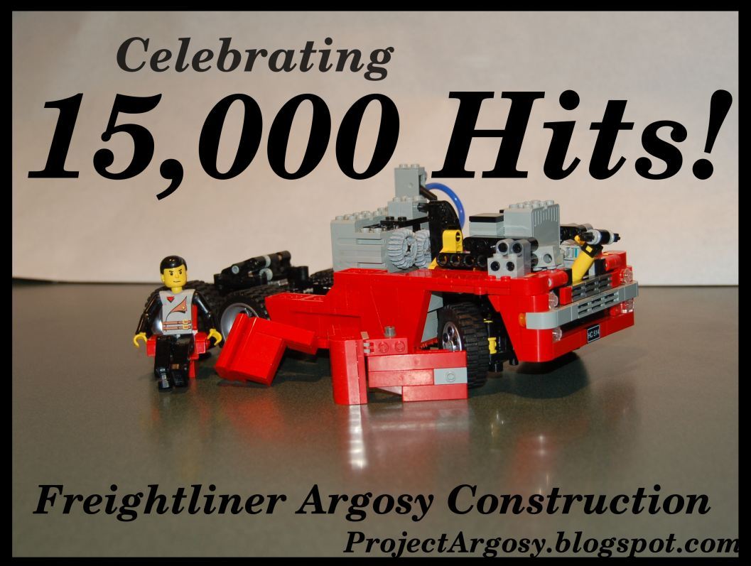
Thursday, April 12, 2007

Finished!

Yesterday I got upwards of fifty pageviews, and thats enough to make me feel guilty enough to post. The Argosy survived the airplane ride both to and from PDX, so I'm happy to present the finished truck.

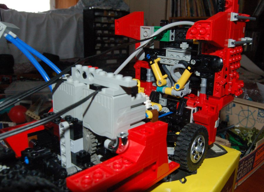
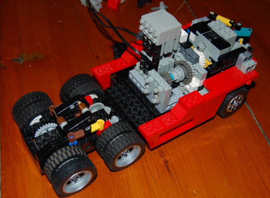
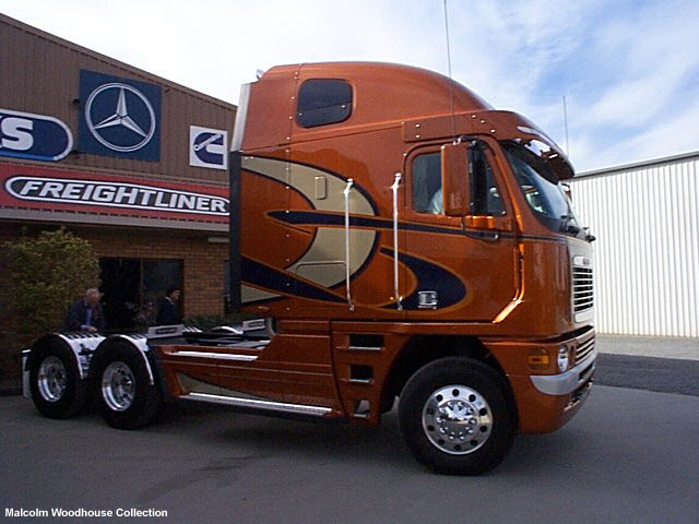
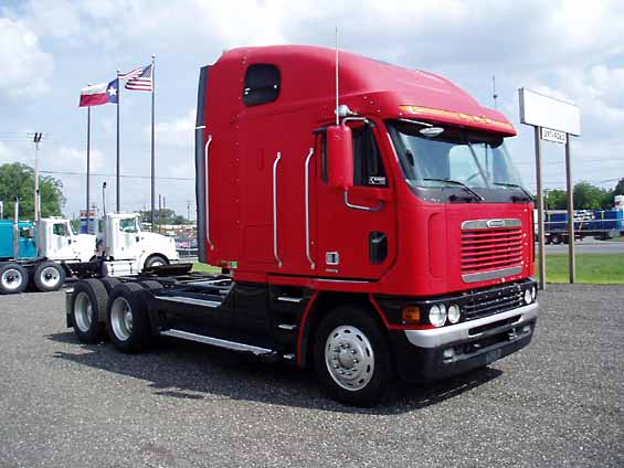
For those of you new to the model, its a fully functional Freightliner Argosy cab-over-engine Tractor Trailer. This includes Forward/Reverse, two speed gearbox, 40° full Ackerman steering with suspension, LED headlights, air compressor, pneumatic steps, and tilting cab! It was started May 2006, taking coutless hours to complete. I brought it to Brickfest 2007, and promised the folks there I would update the blog soon, so here goes!

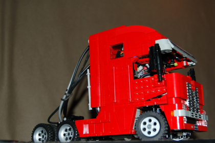
Heres whats new since my last entry. I may go through some parts in more detail later.

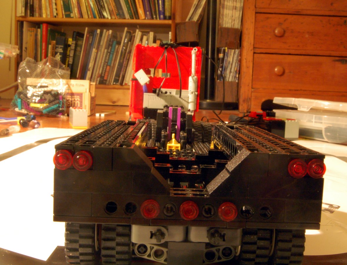
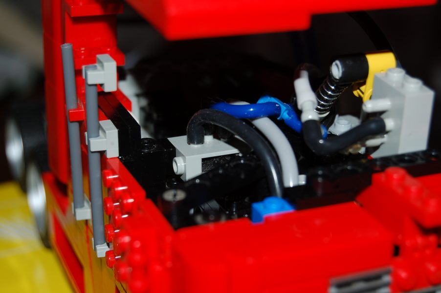
Its got a 9v battery lodged near one of the windows. This powers the carefully hidden master switch. Flip this on and the headlights light up and the air pump starts. The pressure is automatically regulated: I modified a 1cc syringe to push a spring up against a button, turning the pump off. All the electronics are crammed in the back of the cab, hidden (and held in) by a black panel.

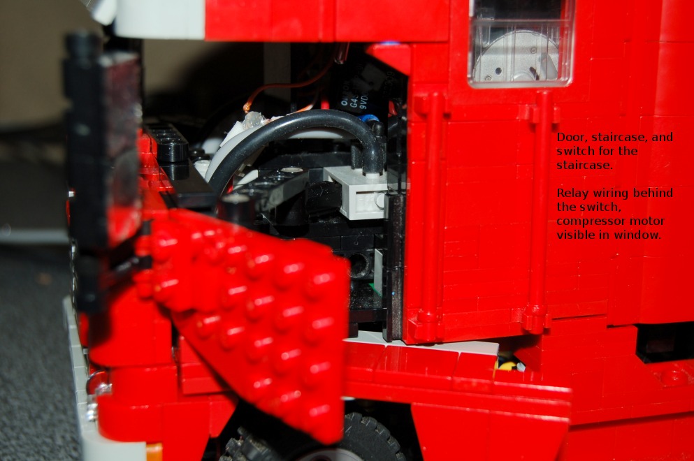
The doors and staircases have been finished and tested. Opening either door will pull a pneumatic switch, which opens a small staircase below it, just like in the real truck. There are air tubes running out of the back of the cab to the controller. They control the two speed gearbox. Also, there is a switch in the back of the cab which controls the air to the trailer.

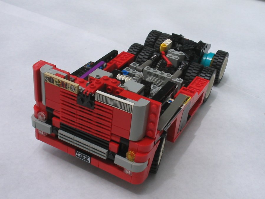
There are also some shiny new mirrors. They are made of glossy heat-to-apply paper, ironed and glued onto Legos. They do not look perfect, but they are at least shiny. Also projectArgosy.blogspot.com is advertised proudly on the front visor.

All in all there is a fair amount of non-Lego on this model. It is difficult to remain a 'purist' model this small without sacrificing funtion. -Most obviously, theres the LEDs, pressure switch, and the decals.
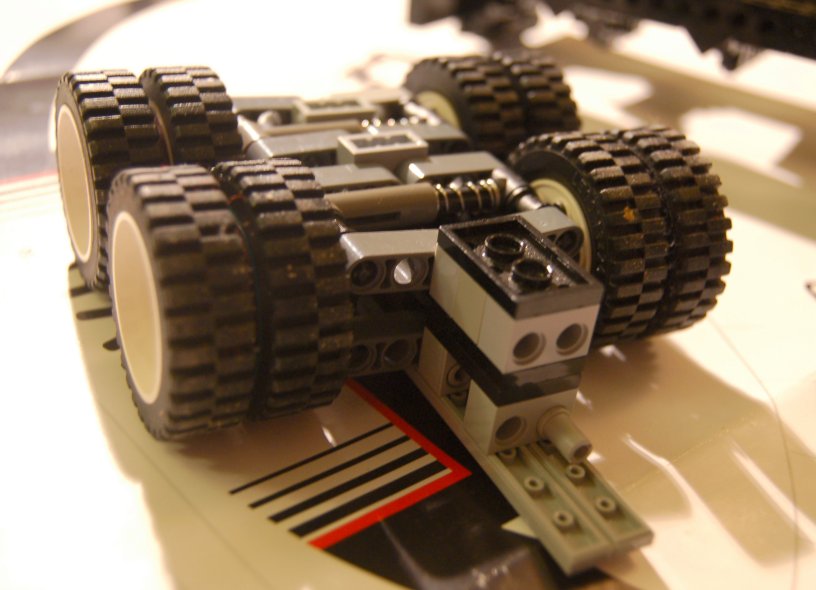
-Various places I've used small metal spacer washers - mainly on the rear axles; they prevent the pins in the Model Team hubs from knocking on the frame.
-I sand-casted a solder 1x2 plate, for use on the fifth wheel. The metal brick adds weight, making the fifth wheel automatically latch when it backs up under a trailer.
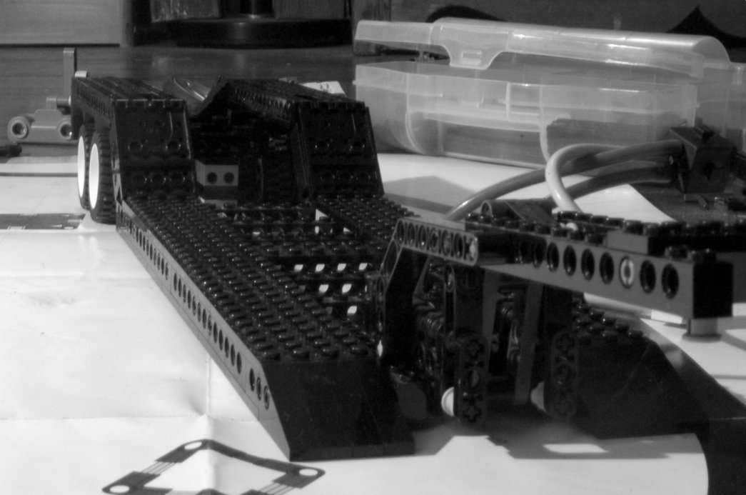
-Since Lego doesn't make elbows for pneumatics, I bored out a few Fischertechnik ones to use various places, especially one the lowboy. They make fitting tubing much more doable.
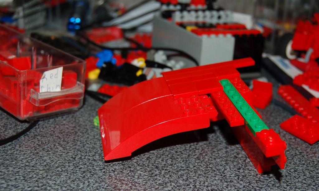
-I used small amount of rubber cement in various areas: on the steering, the gray pins would constantly work themselves out. Adding a little rubber cement is not permanent, but makes them hold better. I also applied some to help hold down the 4x8 slope bricks on the roof. Unfortunately, this did not work for more than a week, and you can notice the small crack in the front in the photos. Unavoidable, because there are no studs or tubes there!

I've also modified some pieces in my attempt to achieve perfection:
-Most obviously, I had to cut a 4x8 slope in half, to accommodate the 14-wide roof.
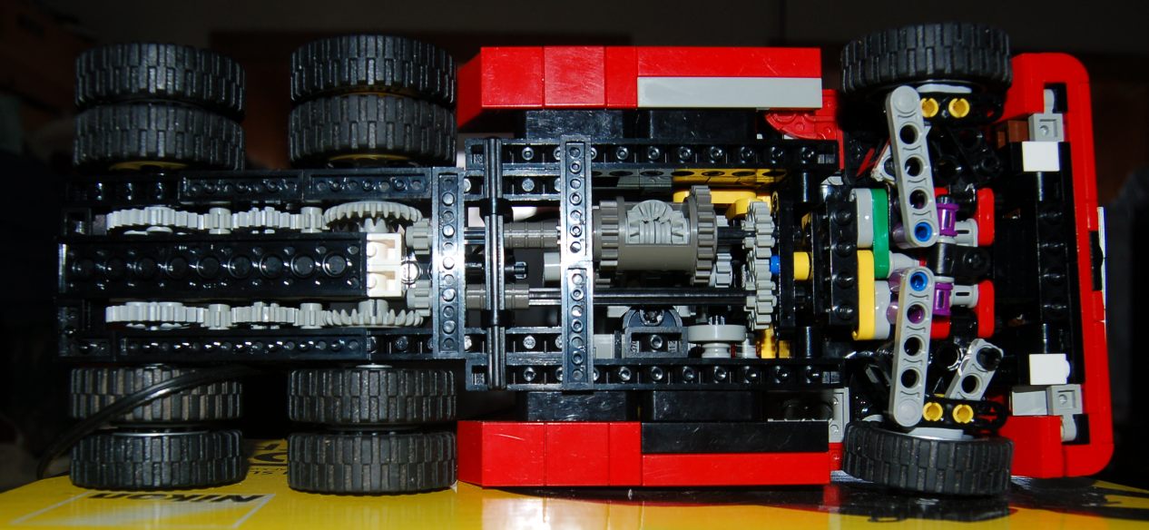
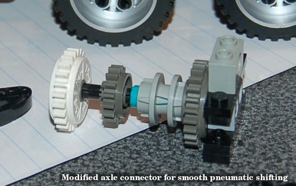
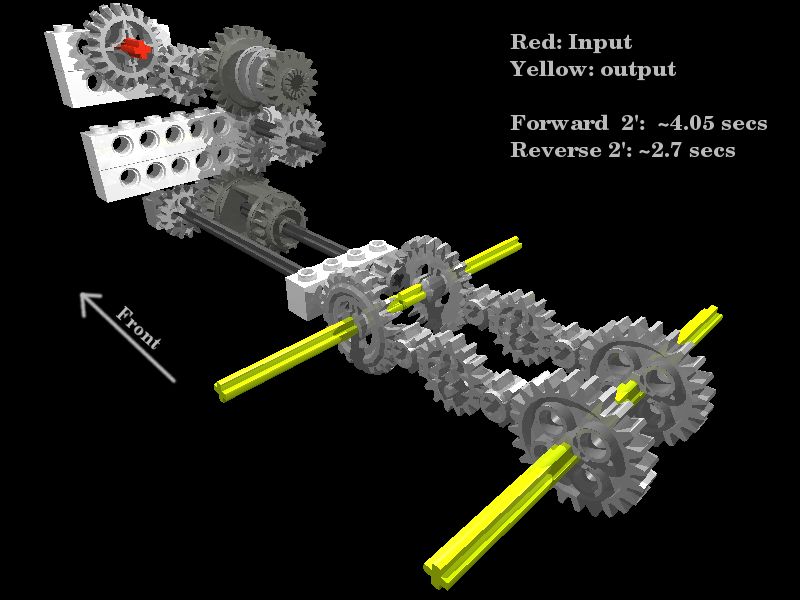
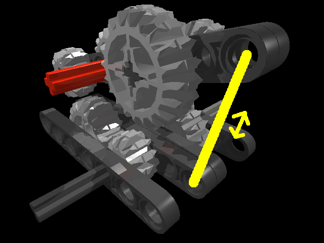
-For the gearbox I filed the ridges off the axle joiner which the driving ring slides on. This allows smooth silent shifting and no need for exorbitant air pressure.
-In the steering assembly, I decided against the gray frictionless pins because they have too much slop. Instead I filed off the friction ridges from black ones and the Pin Double with Axle Hole, resulting in frictionless but stable motion.
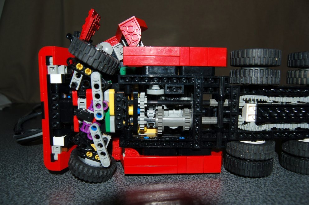
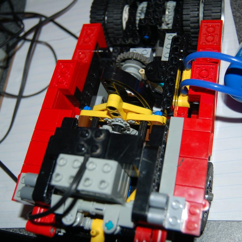
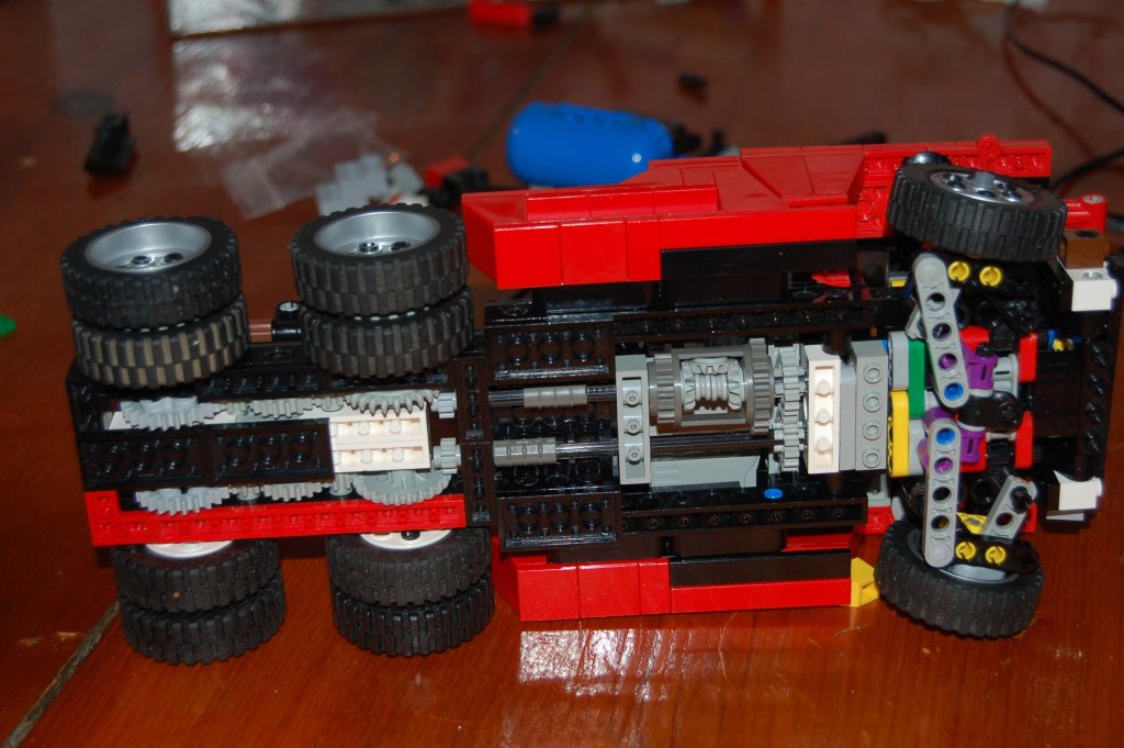
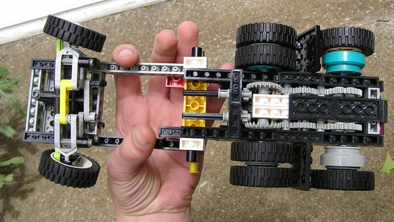
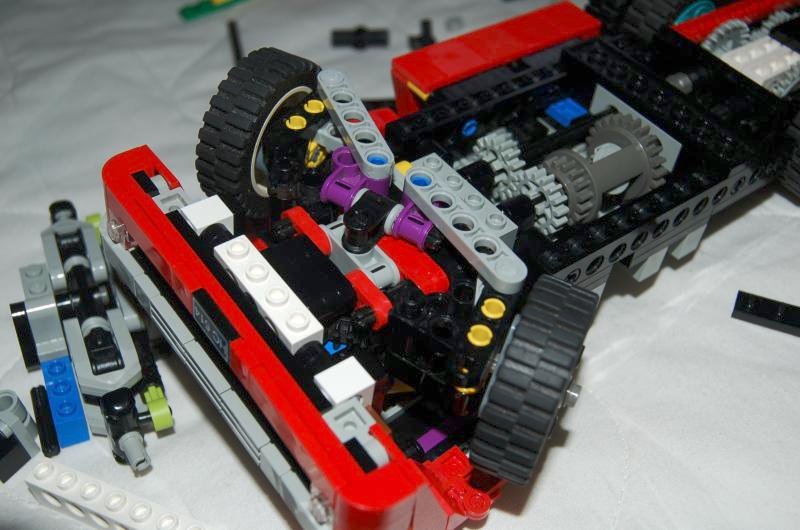
-If you look closely at the picture of the underside of the steering, you can see where I used a technic bush 1/2 sawed in half, and some shortened pins. I also sawed 1x6 thin liftarms in half to create 1x3s.
-For the staircases to work smoothly slide out, the bottom plate needs to have a curved face. This was achieved by turning a round corner 3x3 into a 3x2.
-Each door employs custom a 1x3.5 plate. What else could I do?

As much as I'd never like to admit it, this design is not perfect. :-) When the truck turns, the axles which hold on the front wheels pull out. This needs to be checked about every 0.0011 miles. I believe this is from having too much Ackerman adjustment. Also, the front set of rear axles will begin to pull off, as they are only held on with the 24z crown gear.

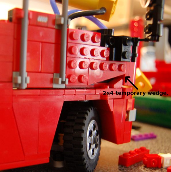
The cab is not completely symmetrical either. For example, the right door uses a 2x4 wedge plate, and the other a 2x3. The 2x4 is is stronger, but the 2x3 looks better, I just couldn't make up my mind!

I opened up the cab to take pictures and the headlights stopped working. One of my solder joints pulled. It was not threaded through the hinge point, and needed an inch or so more wire which it didn't have. This will be difficult to fix, as you don't exactly stick a 3100°F degree soldering iron into a Lego construction.

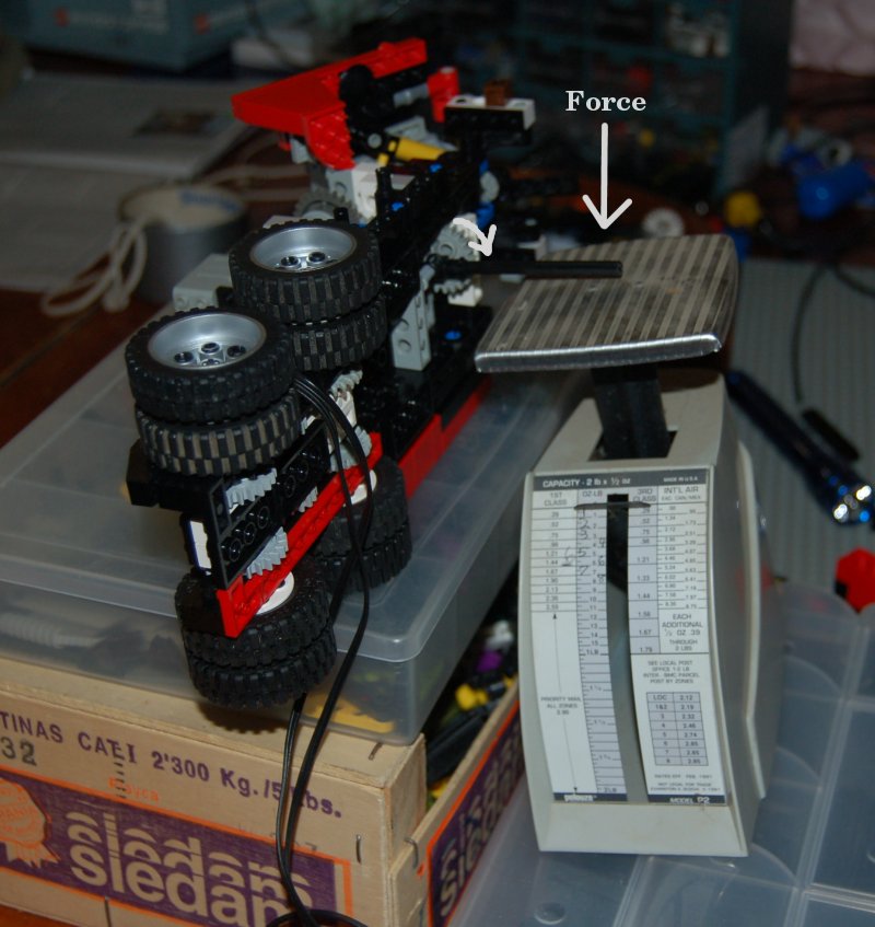
Fun fact: The truck ways just a little over 2.5lbs(1.13kg). Of this weight, about 1.75lbs(0.8kg) is over the front wheels. They still don't flex a bit!

Fun fact: In order to have space for the front axle suspension, theres a 4Ldraw-unit(or half of a plate) gap between the frame and the steering assembly. This required turning 1x4 Technic beams upside-down!

I'm not sure where I'm going next. Time for a break from miniaturization, for sure. I may make some B-train trailers, or give it an NXT brain in a trailer, or some such fun. If I had all the money and time I wanted, I'd build another, larger version, using the Black Cat tires. You never know....

Head over to my Brickshelf Gallery to see all the pictures!

--Peter Ehrlich

Monday, March 26, 2007

Brickfest approaches

The truck and lowboy are finished and packed! Tomorrow I fly to Portland, to display them at Brickfest. I'll finish the build-log when I get back. Hope to see you there!

Saturday, February 24, 2007

Lowboy Prototype

It's been way too long since my last post. It seems I'm taking the large chunks route instead of frequent small posts. Oh well.

For this past months, lots has happened in my Lego world. Firstly, building a robot for the Brickfest Competition has been soaking up some of my free time. The rest of the time I've been faithfully working on the Argosy! Changes: Basic pressure switch, more cab, doors, trailer!

The idea is to have an automatic pressure regulation system. This has been done before in Lego, using a polarity switch, a pneumatic cylinder, and some rubber bands. However, this is unacceptably large.

Instead I've been toying around with a normal 1cc syringe acting as a single-acting pneumatic cylinder. It stretches a rubber band when it extends, and when the pressure drops, it contracts and hits a 8mm square tactile sensor, turning on the motor. It is difficult to tune for the correct pressure range, but I just need to do more experimenting on it.

I've also started building the cab more, putting in windows, handlebars, and the other door. No pictures yet, as it looks odd with a shortage of tiles.

Thanks to goodmantruck.com, I've found some excellent large lowboy pictures. After seeing this trailer I knew it had to be the one. It has a detachable neck - meaning the hitch part comes off for loading and unloading. It's also got big hydraulic cylinders for raising and lowering the trailer height. Total capacity is 52 tons.

That gradually amassing pile of black Technic beams was beckoning, so I decided to take a break from the Argosy proper. Pictured is the first prototype. The neck doesn't detach, some colors are wrong, and the thrid axle isin't made yet.

To my knowledge there are three common types of supsension for trailers: leaf springs, spring-ride, and air-ride. I settled on the second, shock absorbers, - although a heavy load will max them out, it is easier to design and they cost about 1/20 the price of small pneumatic cylinders. With a 14M-wide vehicle, and 8 of those 14 used up by tire, there's not a lot of room left for suspension.

What I have is a straight-and-simple wishbone setup. It works ok, but the ground clearance in the middle is awful. If luck is with me tomorrow, I'll be able to change it slightly to lower the axles 1M relative to the wishbones. Yay! Need more shocks first.

Monday, January 22, 2007

Gears, curves, doors, and electronics.

Ok, so its been a while since my last post. Some of that time was waiting for new parts to arrive, but I've also been very busy. Things that have been changed: There's a roof prototype, gearbox has been stripped down and rebuilt, hopefully stronger, front grill hinge connected, right door prototype made, and I've made an emergency air release valve.

Over these weeks almost every available surface in this room has been covered in bricks - either from disassembled gearbox parts or an NXT project. (For those who are curious, its a Great Ball Contraption idea). Things are looking up now, but I still have to do Physics on my freaking bed.

- Roof -

It's not perfect, but it's good for a first iteration. The biggest slope of about the right curvature is the 4x8x2 curve in red. It matches ok, but it's really not as gentle of a slope as on the real truck. Also, I won't be able to have a skylight, but I suppose that's what happens when you try and combine Legos with Curves. Maybe a sticker will suffice.

There is, unfortunately, another problem with these slopes. As I said they are 4M (1M = 1 stud) wide, and the truck itself is 14M. Lego makes a 2x8x2 curve brick also, but these only come in Reddish Brown and Dark Blue! Either I'll have to paint one of these or saw one of the larger parts in two. Neither of those options I relish - anyone have experience in this department?

Then there's the windshield. I could either go for the "Spotlessly Clean Windshield" technique (read: non-existent) or acquire a large amount of skill in bending polycarbonate plastic in a short period of time. Ideally it would curve at the corners to meet the door-frame, while matching the curve of a 1x2x1.3 tipped sideways.

On the actual truck above the windshield there is a sun-blocker thin metal sheet, usually with small orange lights. I suppose I'll slice up a Schwan's ice cream tub lid, color it with a silver Sharpie, and attach it to the truck somehow. And I'll just skip the lights entirely.

- Gearbox -

I was very happy until I noticed it starting to grind its gears, despite my perfectly strong unbreakable patent pending ultimate gearbox structure design. Boo. Luckily, although there were piles of pneumatics and motors in the cab, on top of the gearbox, this is a tilt-cab vehicle. And because it's Lego, you can detach the cab entirely. (Note: this will be more difficult once pneumatics and electronics are running through the hinge.)

Once freed of the tinkering hindering cab, I could detect the guilty gears with the aid of my trusty mini-maglight. In the end the changes were very small, but the journey was long and difficult. Only time will tell if it is strong enough now. Basically, the gears are held together with a small (but relatively large) studless assembly, which is held to the frame only by two studs.

It's a whole different ball-game when you're rebuilding with extremely strict restrictive limitations for size and attachments. There has to be room for the stair wells, steering motor, frame, and pneumatic shifter. On top of that, the distance between 24z and 16z is very studless incompatible. (Exactly 3 layers, rather than 2 and 2/3.)

In order to withstand the torque of two geared motors stalled in low-gear, everything needs to be quite strong and therefor bulky. Hopefully this won't compromise cornering with trailers too much.

- Bodywork -

Its finally far enough along to try out some doors.Nothing is perfect yet, but it will probably stay close to the way it is now for a while. The doors are mounted, studs out, onto the nose pieces, also studs out. This works amazingly well, for something I was just playing around with. The doors have a slight curve in the front corner just like the real truck. These are also needed in order to have clearance over the studs below, holding the staircase hinge. To make this curve, on the studs-out doors, I need to use 3x2 wedge plates. These don't match the curve and make it impossible to tile the door, but its the best I can do. Maybe a solution will show up later.

On each door is a lever which pulls a pneumatic switch to open the stairs corresponding with the door. With lots of leverage, the stress on the hinge and door from moving the switch is not large, but if necessary the switches can be modified. There are a couple ways to make switches move perfectly smoothly, from cutting off the back panel to replacing the little axle inside.

If I succeed in making a slick polycarbonate windshield, it will need windows on the doors to match. I have no idea how to attach these besides, ahem, glue, but I don't want to go there.

Inside the cab is a pneumatic switch with yellow handle attached to a spring. This is an emergency air release valve. It could be handy to release pressure if I won't be using the model for a while, and don't want it simply leaking out of all the pneumatic seals. Also, it makes a cool noise :-)

- Electronics -

It's High time to have the electrical system made. What will it do? Power headlights, and automatically run an air compressor when the pressure gets low.

There will be a single 9v battery (If it looses charge too fast and there is room, I could have two in parallel.) Everything will be controlled by a master switch inside the cab. Once on, the headlight LEDs will light up and power will flow the chip controlling the compressor.

This chip, a comparator, will turn the motor on and off based upon voltage used, thereby controlling air pressure. If I get it working. This is in lieu of having the standard lego pneumatic cylinder flip a polarity switch when it overpowers a rubber band. Such a system would be much too bulky to fit in the cab, as well as costing me another small cylinder.

If possible, I will install a voltage regulator on the hand-control. This will allow smooth acceleration and variable speeds. More on this later.

- Job List -

Yes, there's more. As the motor for steering is in the cab, I want the cab very firmly attached to the frame, when not in the raised position. This mostly I hope, as I cannot conceive of a way of fitting the necessary parts in. If it worked it would also make the motors more strongly attached to the gearbox. If it won't fit, I'll have to rely on the weight of the cab holding things in place.

Then I get to position cab windows, decide if there are any decals that should be put on, and arrange lights and handlebars. The days are just packed.

Saturday, January 6, 2007

Lowboy planning

I'm still waiting on parts for the roof, but in the meantime there is lots to be thought over. The great thing is, there are many many trailer options. The downside is that there are many, many, trailer options. Current options include a cloth or metal sided B-train (red, duh), a potatoe trailer with unloading conveyor, a hydraulic neck lowboy, or a somehow robotic NXT trailer!

Right now I'm leaning towards the lowboy, because it would have pneumatics, be fun to build, and not tie up my NXT. (Also I have no robotic trailer ideas :P)

It would have 2 or 3 axles, with either pneumatic or sprung suspension, and possibly breaks, depending if the can fit. Heres some pictures:


All images hosted on brickshelf.com

On another note, it looks like Lego will be introducing a new, small, remote control, hopefully geared, minimotor this summer!! I can see where this is heading. Heres the pic:

Saturday, December 30, 2006

Page Views Abound!

Just a quick post to celebrate 15,011 hits to my Brickshelf folder. Sadly, I can't say the same for this blog, but it's getting there!

Update on the model: I've decided to work on the cab and bodywork for a bit. I've got basic plans build for the roof and walls. Probably it's time to spend some money on parts :-/

This (in red) will be for the roof curve:
http://www.bricklink.com/catalogItemPic.asp?P=46413

Wednesday, December 27, 2006

A gearbox that works (and more)

It's been a few days, and in anticipation of 15,000 Brickshelf Gallery hits, I'm writing another entry.

The gearbox design in the last post was terribly inefficient. It had to many gears and much friction; two motors could barely move the truck at high speed. Having an axle push onto a postage scale, I could measure the torque at each point along the drive train. There was much loss at many points. I've rebuilt it now, to a much more compact design.

After getting the gears in, I squeezed in a pneumatic shifter. The switch will be somewhere in the cab, allowing you to switch between 16:24 and 24:16 on the fly. For those of you familiar with the technic driving ring setup, you know it clicks when changing gears. I had to file off the ridges on the axle connector so the small piston would have enough power to slide it.

Although theres some gear slipping still to be fixed, I'm confident this truck will be able to handle a road train!

Next on the TODO list? Get the stairs working slick, fix gear slippage, and thread all seven pneumatic hoses up through where the cab hinge is- to where the compressor will be. Also I should make sure a trailer wond knock into the back of the gearbox on turns.


Thursday, December 21, 2006

Gearbox inching forwards...

The next thing that needs to work is the gearbox. That way I can put up the back of the cab, exhaust pipes, doors, &c, and then figure where everything else needs to be put. Still gotta fit a compressor, air tank, and battery.

The origional gearbox idea didnt work - it would flex slightly and one of the bevel gears would walk off the axle. New plan is to use a griving ring to switch between a 12z 24z gears, selecting a speed. Over the past few days I've tried several arrangements, and I think I've found one that may work, but for one problem. Although it fits nicely and could be strong, It works better driving in reverse than forwards.The only other issue is that the gearbox rotates quite fast - 20:16 from the motor. This means lower torque, but more noise and wear. At least the end speed is right.


Monday, December 18, 2006

The story so far...

It has taken quite a few months to get this far. As mentioned in the last post, it was started in May, quite a while after my previous project, a city bus. The argosy is going to be much more complicated, with more components in less area.

For lack of any better ideas, I started at the rear wheels and frame. The width here would define the rest of the project. I settled on 14 studs wide, enough for a 6-wide frame between the rear wheels. There would be no rear suspension at all, allowing the wheels to lose contact with the ground over hills. For that reason there would be only one differential for both rear axles. It would have to be in the wider section of frame under the cab, and oriented perpendicular to the main axles, to fit best.

Next came the beta frame and steering gear. The standard way to steer wheels of this size was using particualar ball-joint pieces made by Lego for these wheels. You cannot get a very good turning angle with these, and I found a solution later on.

Over the summer I built up the frame and body work, until it looked about like this. Side fuel tanks in, front bumper assembly, front grill, spring-loaded fifth wheel, and a steering motor. At this point almost nothing worked, my building had been sloppy. Fifth wheel and grill hinges didn't work, steering angle was terrible, and the steering itself was loose. It would take a good second of motoring before the wheels began to move. Because of this, and the fact that brickfest had gone by and it was still not ready, the project was retired temporarily.

After a few months, the nagging began to grow, and I decided that after all this time and effort, I was going to see the project through. I pulled out my metaphorical welding iron and got working!

I started with the 5th wheel, as that was the easiest to get into and I had a design thought up from the previous couple months. The new version is much more realistic (right). A trailer easily slides in and locks. It can tilt as in going over hills. It only lacks an uncoupling mechanism. If you look closely in the picture you can see a small metal 1x2 plate on the bottom of one of the brown bricks. I sand casted this from pewter, to serve as a counterweight. This locks the trailer in utilizing gravity rather than a ginormous spring. Possibly a sliding magnet could be used for unhitching the trailer.

More changes to were quick to follow. I dropped the complex mechanism for raising the front grill in favor of one that worked. It now uses a system similar to that in the back hatch of a car, using a pneumatic cylinder with constant pressure to either raise the grill or lock it in place.

It was becoming more and more aparent that the current (at the time) steering setup would not do. It had a poor steering angle/radius, and much play introduced from a long high torque axle running through a (relatively) flexible studless frame. I was tinkering on a system to implement a gear rack before noticing a post on Nicjasno.com about a different way to steer. Using two liftarms not in parallel, you can make the wheel pivot around its center (from above) - without actually having an axle going through the center.

I immediately begun the daunting task of converting this mechanism to something less than half the size. The final design (left) is fairly sound. The purple perpendicualr axle joiners are turned by a 36z gear on the other end of the axle (hidden.) The distance between the blue pins controls the amount of ackermann steering. This setup is similar to whats found on John Deere tractors, as opposed to on the Wikipedia page. The geometry gets annoying when you only have set length liftarms to work with. In the end, however, it turned out better than I could have hoped! The wheels are solid, suspension smooth, and gearing tight. The inner wheel gets a whopping 42° angle, without a large wheelwell. The model will be able to turn around in approximately two feet! (For reference, the outer wheel would be at about 30° max. The proper difference betweent the two is determined by the length of the vehicle.)

The wheels are turned by a motor above, fastened to the hinging cab section. Because of the zero space available, it runs on 6v rather than the normal 9, for less speed and slightly less power. This can be done using the normal lego battery box by making "fake" batteries out of strips of aluminum, to replace two real ones.

In the pictue, you may have noticed the downward-facing bricks. These are used to create a small gap between the steering assembly and the frame above, allowing it to rotate. This allows for humble suspension, but enough to keep most of the wheels on the ground on most road-like surfaces.

Thats it for now! Next up I have a gearbox to worry about: some simple testing showed the one I have now will not hold together, and I mean that quite literally. Also, the bodywork needs to be argued with a little bit more, then maybe I can put the rest of the front back on again.

Sunday, December 17, 2006

About this blog

This is a journal that will eventually cover the entire creation of my current Lego project: a 14-wide model freightliner argosy. Hopefully it will be interesting.

I started work early this year, I think around May/June. I knew I wanted a cabover, for their high manoverability, tilting cab, lack of curves needed on the hood, and large sleeper. Also this truck comes in many forms and variations, so I have room to customise. Why red? Why not? I can't even imagine it in another color today.

Its amazingly hard to find plans or data about this truck, so I'm just doing it all by eye. They are also extremely rare in america, I can't find a dealer with one for hundreds of miles. So, I just have pictures to go on.

I have a certain number of goals for this truck, most of them to be crammed into the sleeper and cab. They include: two-speed drive (with pneumatic shifting and differential,) full Ackermann steering, tilting cab, air compressor, folding pneumatic steps, pneumatic front grill, headlights, and a functional 5th wheel. Possible? I sure hope so. More static features might include a custom polycarbonate windshield and chrome exhaust pipe(s)!