The story so far...
It has taken quite a few months to get this far. As mentioned in the last post, it was started in May, quite a while after my previous project, a city bus. The argosy is going to be much more complicated, with more components in less area.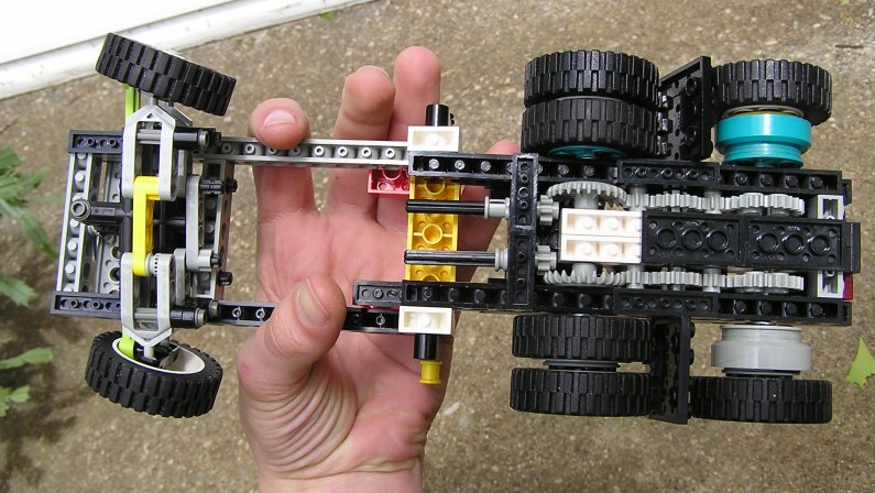 For lack of any better ideas, I started at the rear wheels and frame. The width here would define the rest of the project. I settled on 14 studs wide, enough for a 6-wide frame between the rear wheels. There would be no rear suspension at all, allowing the wheels to lose contact with the ground over hills. For that reason there would be only one differential for both rear axles. It would have to be in the wider section of frame under the cab, and oriented perpendicular to the main axles, to fit best.
Next came the beta frame and steering gear. The standard way to steer wheels of this size was using particualar ball-joint pieces made by Lego for these wheels. You cannot get a very good turning angle with these, and I found a solution later on.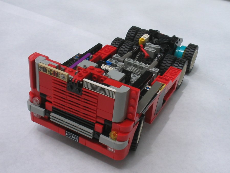 Over the summer I built up the frame and body work, until it looked about like this. Side fuel tanks in, front bumper assembly, front grill, spring-loaded fifth wheel, and a steering motor. At this point almost nothing worked, my building had been sloppy. Fifth wheel and grill hinges didn't work, steering angle was terrible, and the steering itself was loose. It would take a good second of motoring before the wheels began to move. Because of this, and the fact that brickfest had gone by and it was still not ready, the project was retired temporarily.
After a few months, the nagging began to grow, and I decided that after all this time and effort, I was going to see the project through. I pulled out my metaphorical welding iron and got working! I started with the 5th wheel, as that was the easiest to get into and I had a design thought up from the previous couple months. The new version is much more realistic (right). A trailer easily slides in and locks. It can tilt as in going over hills. It only lacks an uncoupling mechanism. If you look closely in the picture you can see a small metal 1x2 plate on the bottom of one of the brown bricks. I sand casted this from pewter, to serve as a counterweight. This locks the trailer in utilizing gravity rather than a ginormous spring. Possibly a sliding magnet could be used for unhitching the trailer.
More changes to were quick to follow. I dropped the complex mechanism for raising the front grill in favor of one that worked. It now uses a system similar to that in the back hatch of a car, using a pneumatic cylinder with constant pressure to either raise the grill or lock it in place.
It was becoming more and more aparent that the current (at the time) steering setup would not do. It had a poor steering angle/radius, and much play introduced from a long high torque axle running through a (relatively) flexible studless frame. I was tinkering on a system to implement a gear rack before noticing a post on Nicjasno.com about a different way to steer. Using two liftarms not in parallel, you can make the wheel pivot around its center (from above) - without actually having an axle going through the center.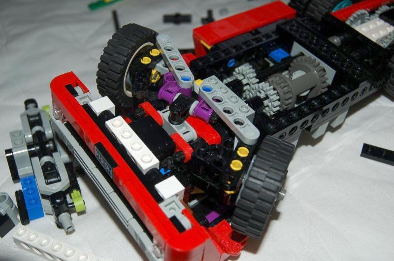 I immediately begun the daunting task of converting this mechanism to something less than half the size. The final design (left) is fairly sound. The purple perpendicualr axle joiners are turned by a 36z gear on the other end of the axle (hidden.) The distance between the blue pins controls the amount of ackermann steering. This setup is similar to whats found on John Deere tractors, as opposed to on the Wikipedia page. The geometry gets annoying when you only have set length liftarms to work with. In the end, however, it turned out better than I could have hoped! The wheels are solid, suspension smooth, and gearing tight. The inner wheel gets a whopping 42° angle, without a large wheelwell. The model will be able to turn around in approximately two feet! (For reference, the outer wheel would be at about 30° max. The proper difference betweent the two is determined by the length of the vehicle.)
The wheels are turned by a motor above, fastened to the hinging cab section. Because of the zero space available, it runs on 6v rather than the normal 9, for less speed and slightly less power. This can be done using the normal lego battery box by making "fake" batteries out of strips of aluminum, to replace two real ones.
In the pictue, you may have noticed the downward-facing bricks. These are used to create a small gap between the steering assembly and the frame above, allowing it to rotate. This allows for humble suspension, but enough to keep most of the wheels on the ground on most road-like surfaces.
Thats it for now! Next up I have a gearbox to worry about: some simple testing showed the one I have now will not hold together, and I mean that quite literally. Also, the bodywork needs to be argued with a little bit more, then maybe I can put the rest of the front back on again.